Building It Step By Step
React Flow Abstraction Layer
Learn about the abstraction layer that sits on top of React Flow.
Getting Started
Navigate to the corresponding folder:
cd step-1-react-flow-abstration-layer
Install the dependencies:
npm install
Then run the project:
npm run dev
React Flow Abstraction Layer
To generate the visual representation of a workflow, the system uses an abstraction layer that sits on top of React Flow rather than using it directly, as shown below.
// src/shared/kits/workflow/index.tsx

// ...

export function WorkflowView() {
  const flows = useMemo(() => createFlows(), []);

  const onFlowsChange = useCallback((changes: TypedFlowsChange[]) => {
    console.log(changes);
  }, []);

  return (
    <FlowsView
      flows={flows}
      onFlowsChange={onFlowsChange}
      nodeTypes={nodeTypes}
      edgeTypes={edgeTypes}
    />
  );
}
This abstraction layer is in src/shared/lib/flows and exposes a FlowsView component, which accepts the following props:
flows: The visual representation of the workflow.onFlowsChange: Called when the user selects, drags, or drops a node.nodeTypes: The available node types.edgeTypes: The available edge types.
The Structure of a Workflow View
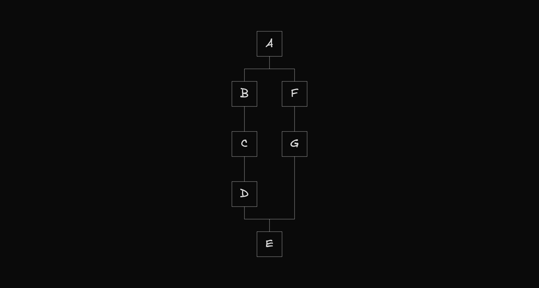
When a workflow state is converted into its visual representation, the result always takes a predictable shape. This is because the visual representation follows a specific structure.
At its most basic level, the workflow can be seen as a sequence of nodes.

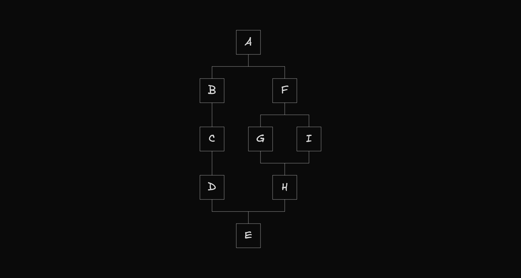
At certain points, a node can create a fork, where the flow branches into multiple paths, with each path acting as a separate flow that eventually merges back into the main one.
Since each path is itself a flow, it can also create its own fork, forming a recursive structure.
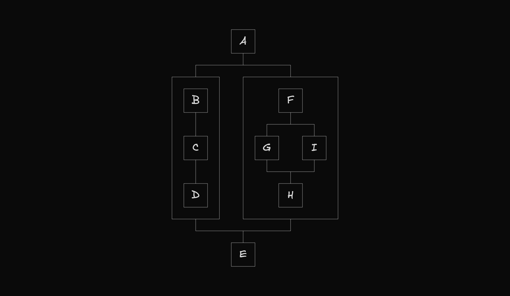
Some nodes also act as containers, holding nested flows that follow the same structure.
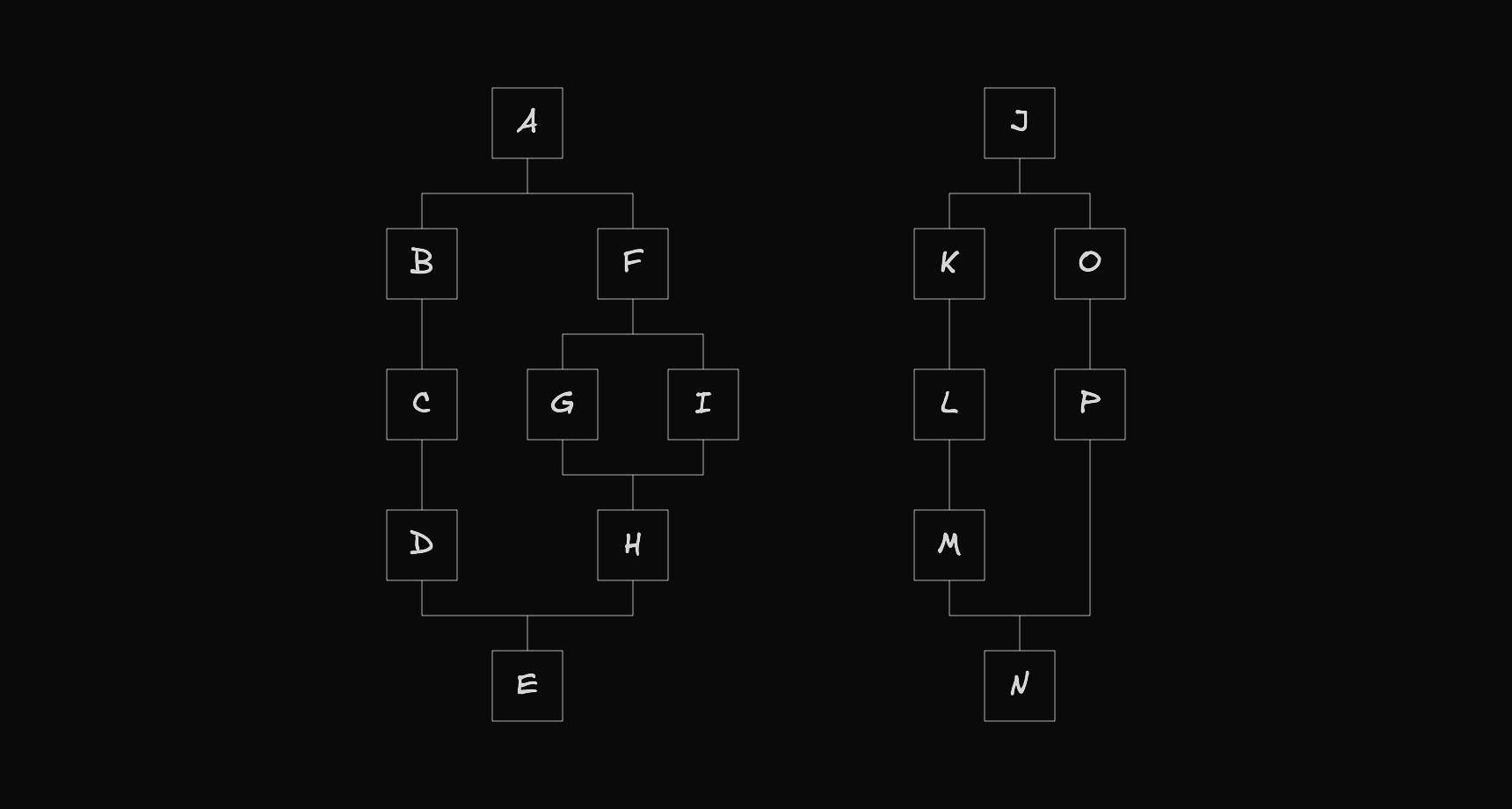
Finally, a workflow view representation can also include multiple top-level flows.
The Code of a Workflow View
The visual representation of a workflow is defined using the Flows type.
// src/shared/lib/flows/types/flows.ts

// ...

export interface Flows<T extends NodeEntity, U extends EdgeEntity> {
  roots: FlowNode<T, U>[];
  nodes: Map<string, FlowNode<T, U>>;
}

// ...
It has two properties:
roots: The list of root nodes, one per flow.nodes: A map of each node's id to the node itself.
The createFlows function below returns an object of this type.
// src/shared/kits/workflow/flows.ts

// ...

export function createFlows(): TypedFlows {
  // ...

  const roots: TypedFlowNode[] = [A];
  const nodes: Map<string, TypedFlowNode> = new Map();

  nodes.set(A.id, A);
  nodes.set(B.id, B);
  nodes.set(C.id, C);
  nodes.set(D.id, D);
  nodes.set(E.id, E);
  nodes.set(F.id, F);
  nodes.set(G.id, G);
  nodes.set(H.id, H);
  nodes.set(I.id, I);

  return {
    roots: roots,
    nodes: nodes,
  };
}
Regular nodes are called component nodes and are created as shown below.
const A: TypedFlowNode = {
  id: "A",
  type: "component",
  entity: {
    type: "block",
    meta: {},
    data: {
      name: "A",
    },
  },
  selected: false,
  position: {
    x: 0,
    y: 0,
  },
  positionAbsolute: {
    x: 0,
    y: 0,
  },
  size: {
    w: 80,
    h: 80,
  },
  gaps: {
    next: 40,
  },
  next: [],
  prev: [],
  parent: null,
};
Nodes that can contain flows inside are called container nodes and are created like this.
const G: TypedFlowNode = {
  id: "G",
  type: "container",
  entity: {
    type: "container",
    meta: {},
    data: {
      size: {
        w: 0,
        h: 0,
      },
    },
  },
  selected: false,
  position: {
    x: 0,
    y: 0,
  },
  positionAbsolute: {
    x: 0,
    y: 0,
  },
  size: {
    w: 0,
    h: 0,
  },
  room: {
    x: 40,
    y: 40,
  },
  gaps: {
    into: 40,
    next: 40,
  },
  into: [],
  next: [],
  prev: [],
  parent: null,
};
Edges are created as follows.
const AtoB: TypedFlowEdge = {
  id: "A-B",
  entity: { type: "line", data: {} },
  length: 40,
  source: A,
  target: B,
};
To connect nodes, the next and prev arrays are updated accordingly.
A.next.push({ edge: AtoB, node: B });
B.prev.push({ edge: AtoB, node: A });
To insert a flow into a container, the root node is added to its into array.
G.into.push(H);
Finally, node positions are computed using the autoLayout utility function.
autoLayout(A);
The Auto Layout Algorithm
The algorithm to compute node positions can be found in the following file.
// src/shared/lib/flows/utils/auto-layout.ts

// ...

/**
 * Automatically sets the position of each node in the flow, starting from the root.
 * The root node keeps its original position, and all other nodes are positioned relative to it.
 * Also updates the size of container nodes based on their children.
 *
 * For a deeper understanding of the algorithm, see:
 * https://www.workflowkit.app/blog/articles/react-flow-auto-layout
 */
export function autoLayout<T extends NodeEntity, U extends EdgeEntity>(
  root: FlowNode<T, U>,
) {
  setContainerNodes(root);
  const dimensions = getDimensionsFlow(root);
  setPositions(root, dimensions, {
    x: root.position.x - (dimensions.flow.l - root.size.w / 2),
    y: root.position.y,
  });
  setPositionsAbsolute(root);
}

// ...
If you want to learn how the algorithm works, you can visit the following link, which explains the main reasoning behind how node positions are computed.
Node and Edge Types
When creating the Flows object, we must use the available node and edge types, which are defined in the file shown below.
// src/shared/kits/workflow/entities/index.ts

export { nodeTypes, type NodeEntity } from "./nodes";
export { edgeTypes, type EdgeEntity } from "./edges";
Node Types
The node types are created in the following file.
// src/shared/kits/workflow/entities/nodes/index.tsx

import type { NodeTypes } from "@xyflow/react";

import Block, { BlockEntity } from "./block";
import Container, { ContainerEntity } from "./container";

export type NodeEntity = BlockEntity | ContainerEntity;

export const nodeTypes: NodeTypes = {
  block: Block,
  container: Container,
};
We export a nodeTypes object where each key is a node type identifier and each value is its corresponding component, along with a NodeEntity type.
The NodeEntity type is defined as a union of objects with the following properties:
type: Identifier for the node type.meta: Data that is not used by the component.data: Data that is used by the component.
The following file shows how a component node is created.
// src/shared/kits/workflow/entities/nodes/block.tsx

import { Handle, Position, NodeProps, Node } from "@xyflow/react";

export interface BlockEntity {
  type: "block";
  meta: Record<never, never>;
  data: {
    name: string;
  };
}

export default function Block({
  data,
}: NodeProps<Node<BlockEntity["data"], BlockEntity["type"]>>) {
  return (
    <>
      <Handle type="target" position={Position.Top} />
      <div className="flex size-20 items-center justify-center rounded-xl border border-gray-300 bg-white px-3">
        <p className="font-mono text-base font-medium text-gray-900">
          {data.name}
        </p>
      </div>
      <Handle type="source" position={Position.Bottom} />
    </>
  );
}
The following file shows how a container node is created.
// src/shared/kits/workflow/entities/nodes/container.tsx

import { Handle, Position, NodeProps, Node } from "@xyflow/react";

export interface ContainerEntity {
  type: "container";
  meta: Record<never, never>;
  data: {
    size: {
      w: number;
      h: number;
    };
  };
}

export default function Container({
  data,
}: NodeProps<Node<ContainerEntity["data"], ContainerEntity["type"]>>) {
  return (
    <>
      <Handle type="target" position={Position.Top} />
      <div
        className="rounded-xl border border-gray-300"
        style={{ width: data.size.w, height: data.size.h }}
      />
      <Handle type="source" position={Position.Bottom} />
    </>
  );
}
When creating a container node, a size prop must be defined to represent its dimensions. The autoLayout function calculates this size and assigns it to the prop.
Edge Types
The edge types are created in the following file.
// src/shared/kits/workflow/entities/edges/index.tsx

import type { EdgeTypes } from "@xyflow/react";

import Line, { LineEntity } from "./line";

export type EdgeEntity = LineEntity;

export const edgeTypes: EdgeTypes = {
  line: Line,
};
The following file shows how an edge is created.
// src/shared/kits/workflow/entities/edges/line.tsx

import type { Edge, EdgeProps } from "@xyflow/react";

import { BaseEdge } from "@xyflow/react";

import { getSmoothStepPath } from "@/shared/lib/flows";

export interface LineEntity {
  type: "line";
  data: Record<never, never>;
}

export default function Line({
  id,
  sourceX,
  sourceY,
  targetX,
  targetY,
  style,
}: EdgeProps<Edge<LineEntity["data"], LineEntity["type"]>>) {
  const path = getSmoothStepPath({
    sourceX,
    sourceY,
    targetX,
    targetY,
    offset: 16,
    radius: 12,
  });
  return (
    <BaseEdge
      id={id}
      path={path}
      style={{
        ...style,
        stroke: `var(--color-gray-300)`,
        strokeWidth: 1,
        strokeOpacity: 1,
      }}
    />
  );
}
As you can observe, we're using the getSmoothStepPath utility function to create the edge. This is the function we should use whenever we need to create an edge in our workflow.
Select, Drag and Drop
Whenever a node is selected, dragged, or dropped, the onFlowsChange callback is invoked with an array of change objects describing the updates to perform.
These changes are described by the following type definitions.
// src/shared/lib/flows/types/flows-change.ts

// ...

export type FlowsChange<T extends NodeEntity, U extends EdgeEntity> =
  | NodeSelectChange<T, U>
  | NodeDragChange<T, U>
  | NodeDropChange<T, U>;

export interface NodeSelectChange<T extends NodeEntity, U extends EdgeEntity> {
  type: "select";
  node: FlowNode<T, U>;
  selected: boolean;
}

export interface NodeDragChange<T extends NodeEntity, U extends EdgeEntity> {
  type: "drag";
  node: FlowNode<T, U>;
  position: {
    x: number;
    y: number;
  };
  positionAbsolute: {
    x: number;
    y: number;
  };
}

export interface NodeDropChange<T extends NodeEntity, U extends EdgeEntity> {
  type: "drop";
  node: FlowNode<T, U>;
}