28 March 2026
React Flow Auto Layout: How to Automatically Position Nodes for Workflow Editors
React Flow gives you full control over where nodes are placed — which is great until you realize you don't want to place them yourself. For workflow editors, manually positioning every node is tedious and fragile. A layout algorithm handles it for you, so you can focus on the logic instead.
There are established libraries for this — Dagre, ELK, and D3-Hierarchy — but they're designed for specific graph structures and may not fit the needs of a workflow editor. That's why I designed one from scratch.
What the Algorithm Does
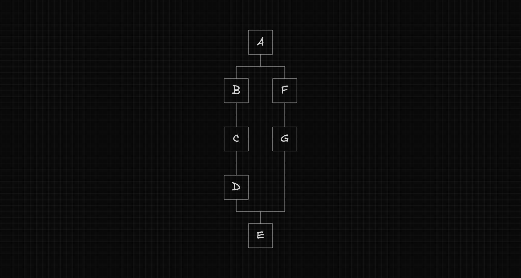
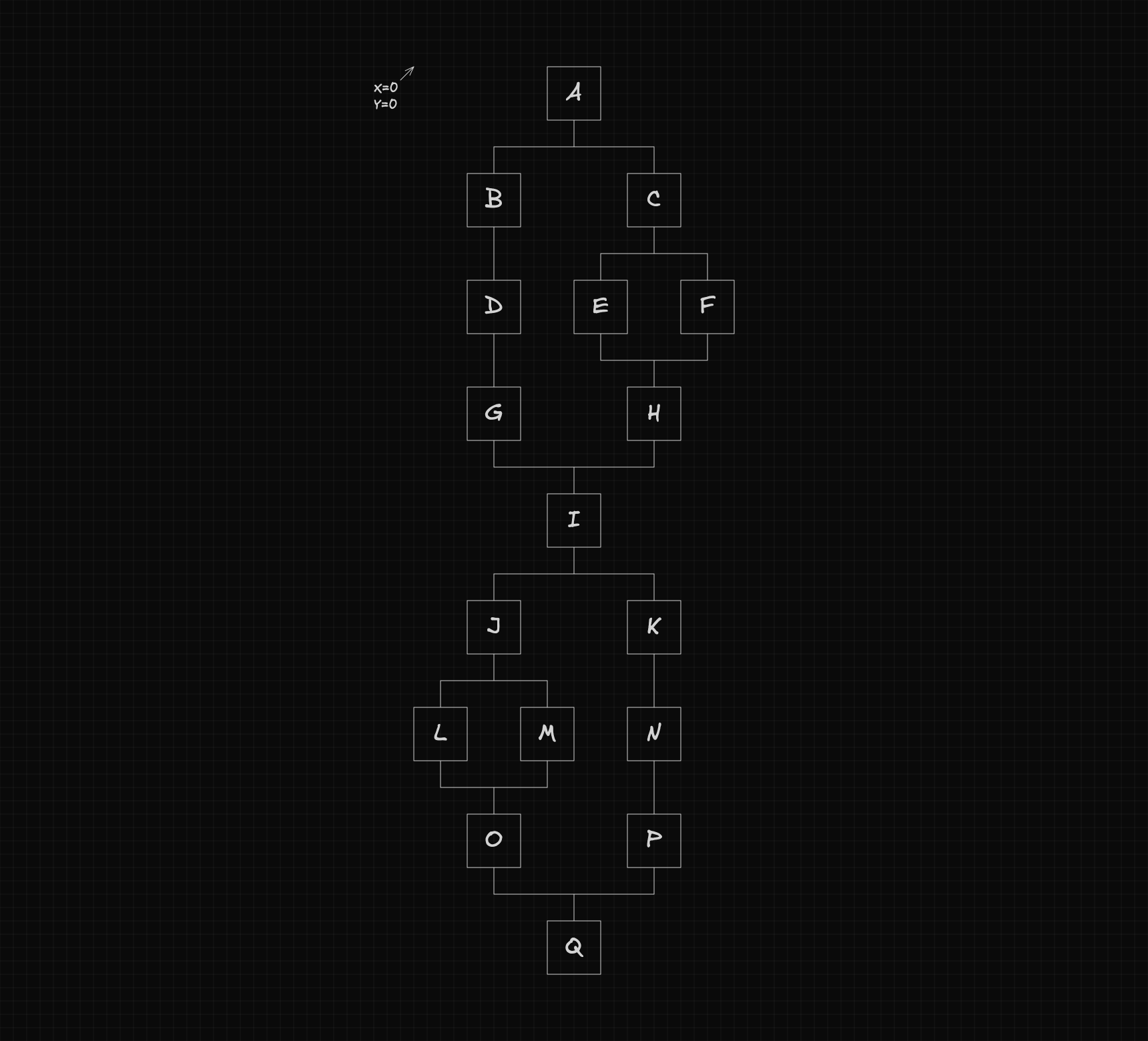
I needed a layout algorithm tailored to workflow editors — not a general-purpose graph layout. Specifically, I wanted a function that could take a workflow structure like this:
...automatically calculate each node's position, update the original flow with those coordinates, and return the total dimensions of the workflow:
In this article I'll walk through how that algorithm works — the reasoning behind the key decisions, the constraints that shaped the solution, and how all the pieces fit together.
The Structure of a Workflow
Before diving into how the algorithm works, we first need to understand how the workflow is structured.
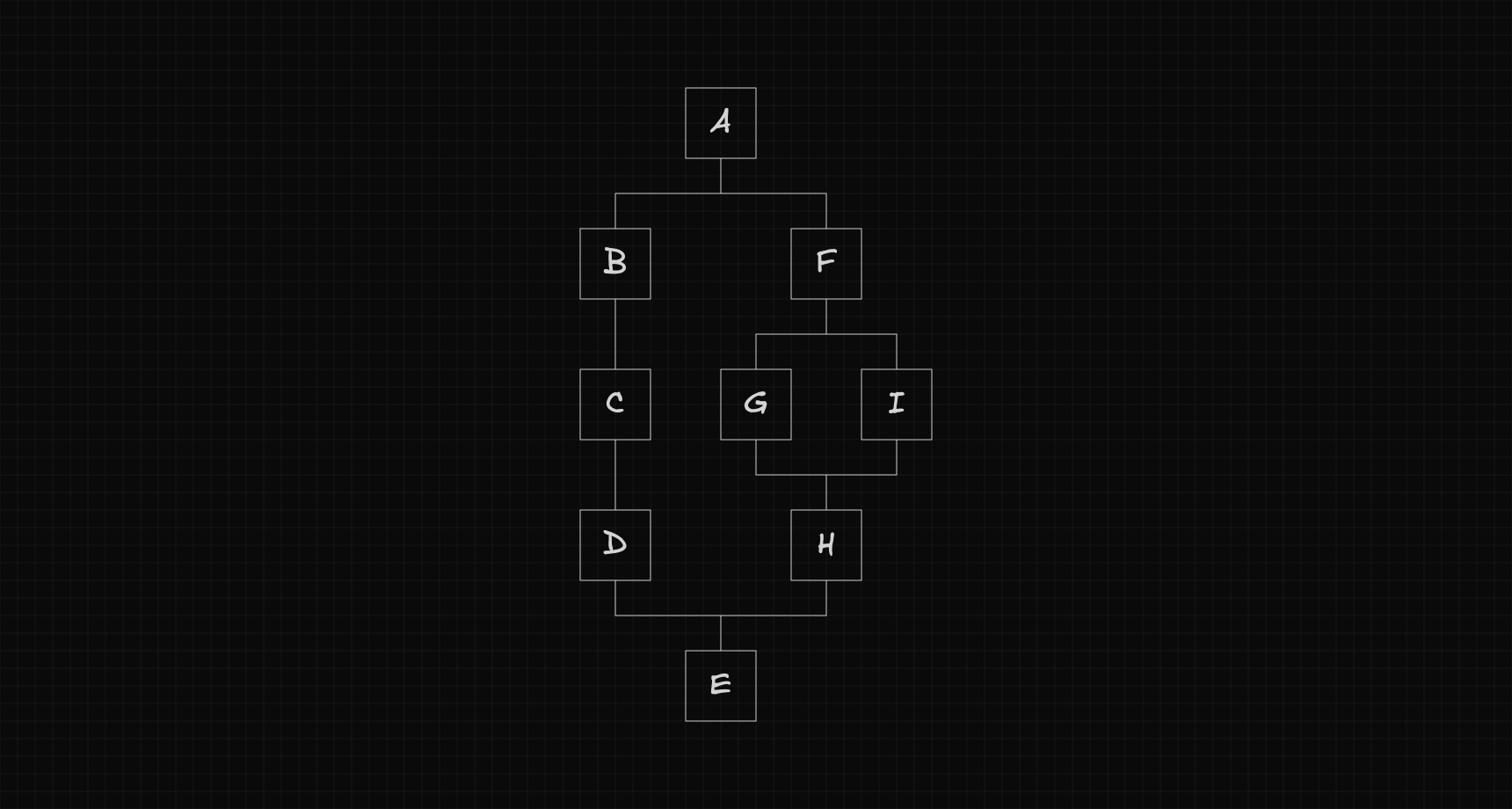
At its most basic level, the workflow can be seen as a sequence of nodes.

At certain points, a node can create a fork, where the flow branches into multiple paths, with each path acting as a separate flow that eventually merges back into the main one.
Since each path is itself a flow, it can also create its own fork, forming a recursive structure.
Code Representation
To represent this workflow in code, we define a TypeScript interface describing what a node looks like.
export interface Node {
  id: string;
  position: {
    x: number;
    y: number;
  };
  size: {
    w: number;
    h: number;
  };
  next: Node[];
  prev: Node[];
}
Configuration
To keep the layout flexible, the distance between nodes is controlled by a configurable gap. This gap defines how much horizontal and vertical spacing should be left between each node.
interface Config {
  gap: {
    x: number;
    y: number;
  };
}

export const config: Config = {
  gap: {
    x: 4,
    y: 4,
  },
};
The Notation We'll Use
Before diving into the algorithm, let's define the notation we'll use throughout the explanation.
Node
Each node is represented by a single letter, such as , , or .

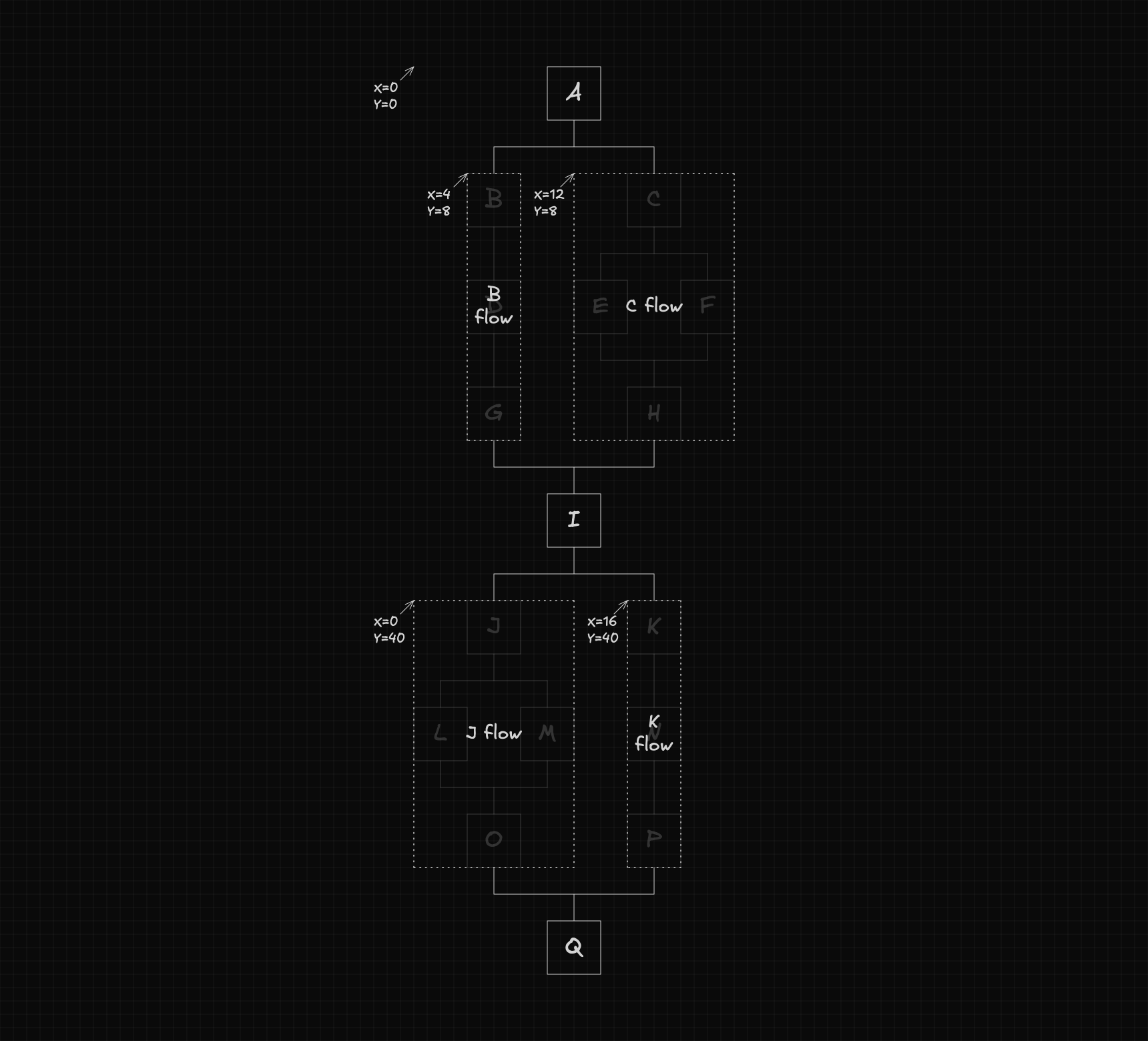
Flow
A flow is identified by the letter of its root node, followed by the word flow.
For example, a flow starting at node is written as .
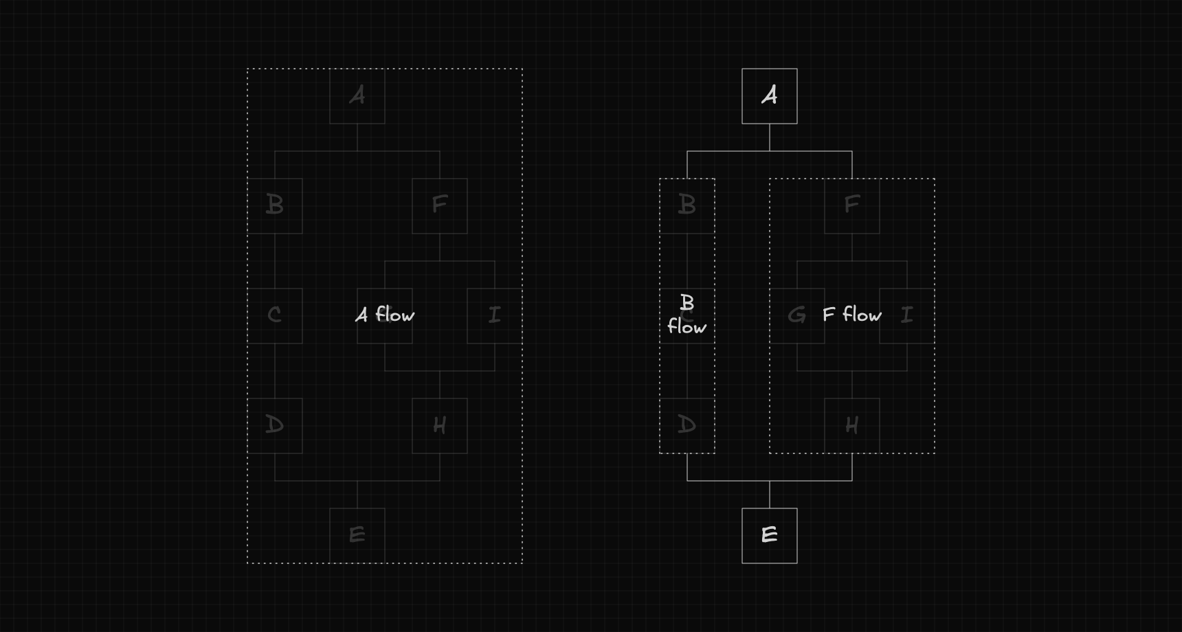
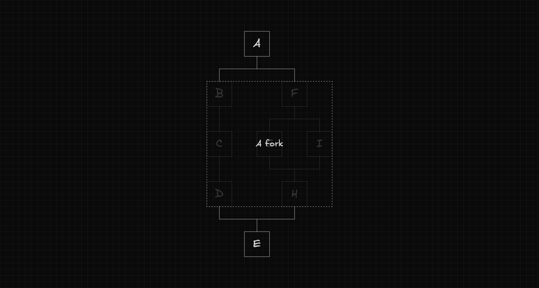
Fork
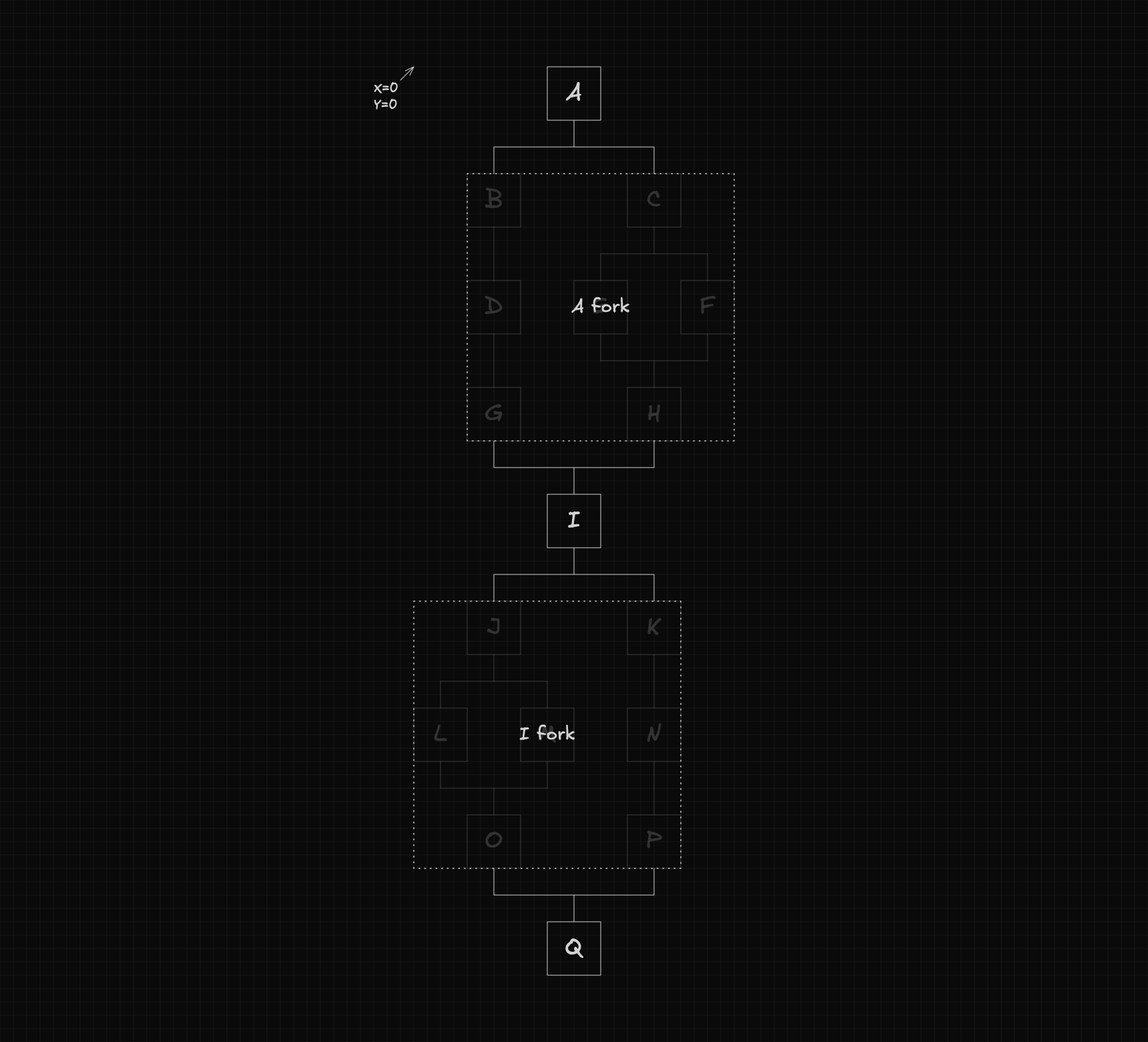
A fork is defined by the letter of the node that creates it, followed by the word fork.
For instance, if node creates a fork, we'll refer to it as .
Attributes
We'll use subscripts to represent the geometric attributes of nodes, flows, and forks.
- : The x-coordinate of node .
- : The y-coordinate of node .
- : The width of node .
- : The height of node .
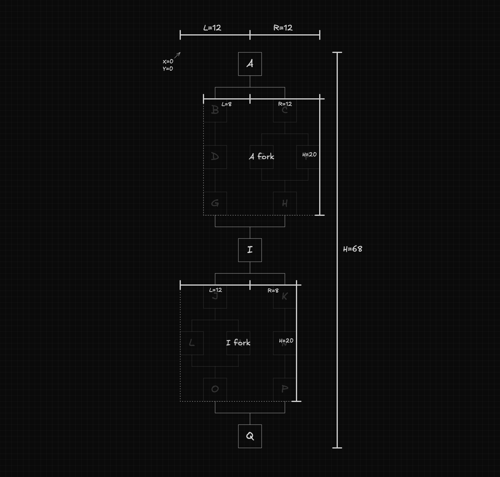
- : The distance from the left edge of node to the center of the workflow.
- : The distance from the right edge of node to the center of the workflow.
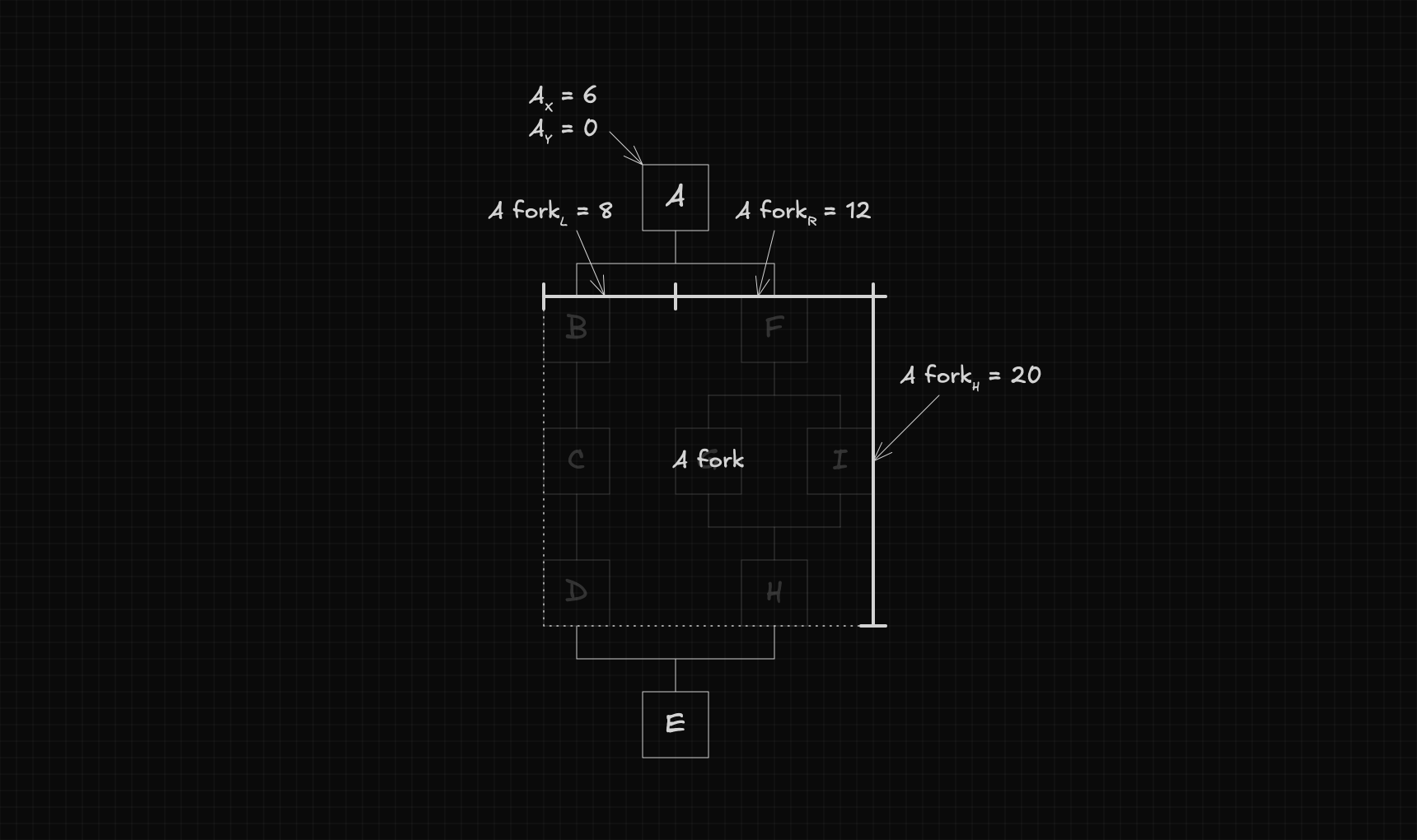
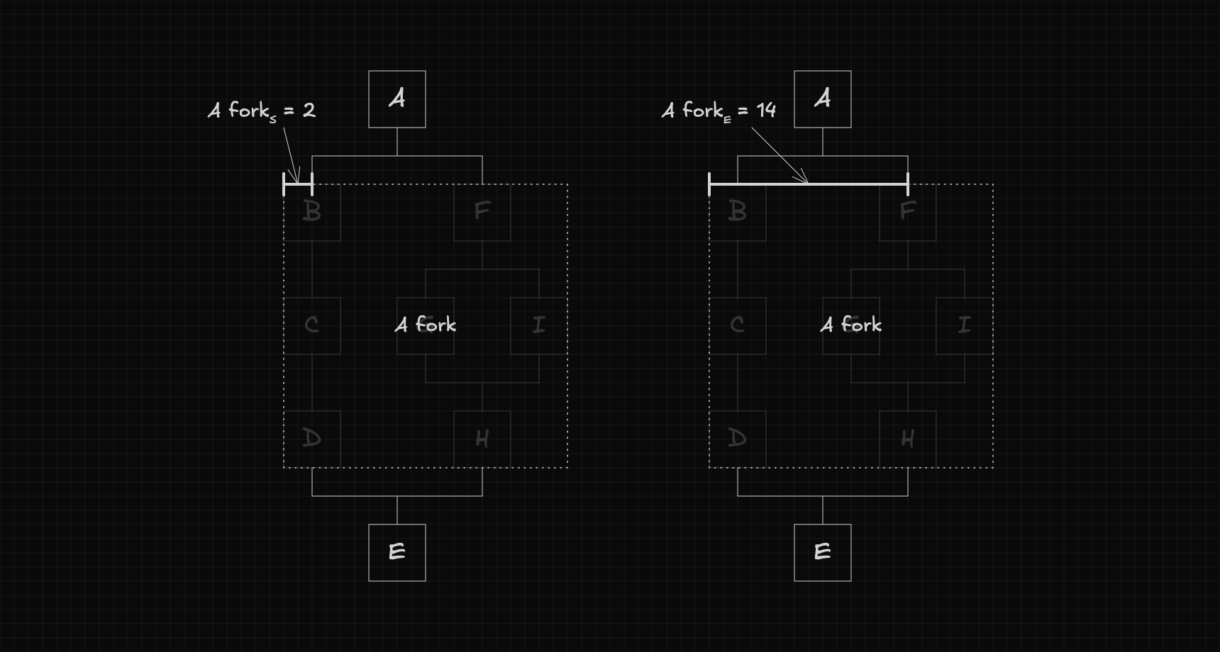
When we're talking about forks, we use two additional attributes:
- : The start of the fork — the distance between its left edge and the center of its first flow.
- : The end of the fork — the distance between its left edge and the center of its last flow.
The Algorithm Explained
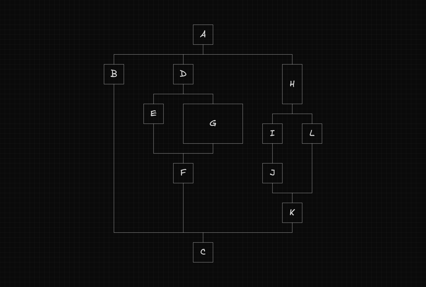
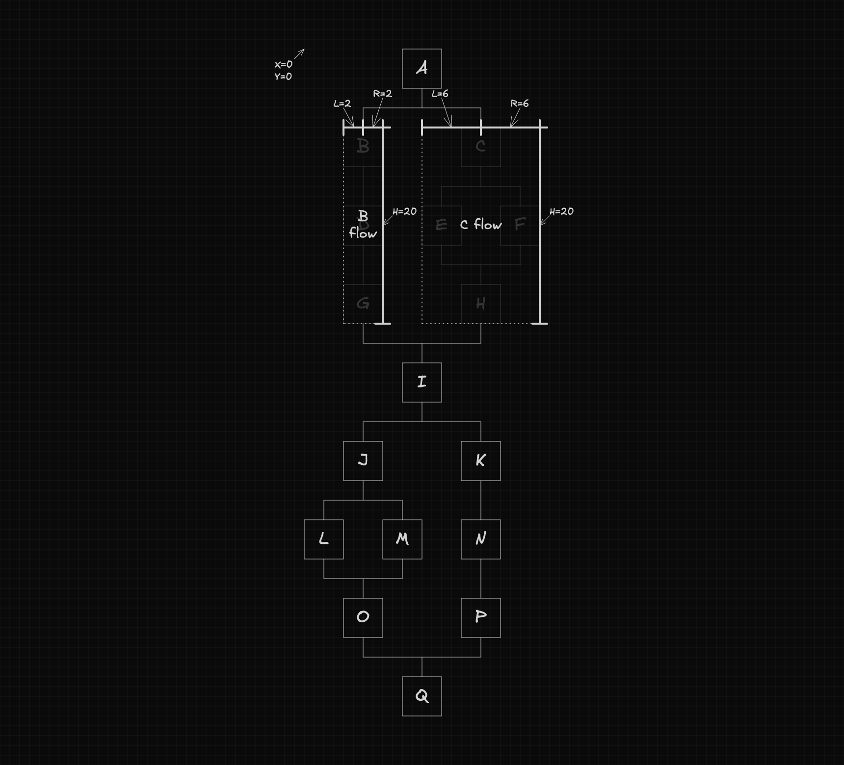
Now that the main concepts are clear, we can start exploring how the algorithm works. Throughout this explanation, we’ll use the example below as our reference.
Computing positions
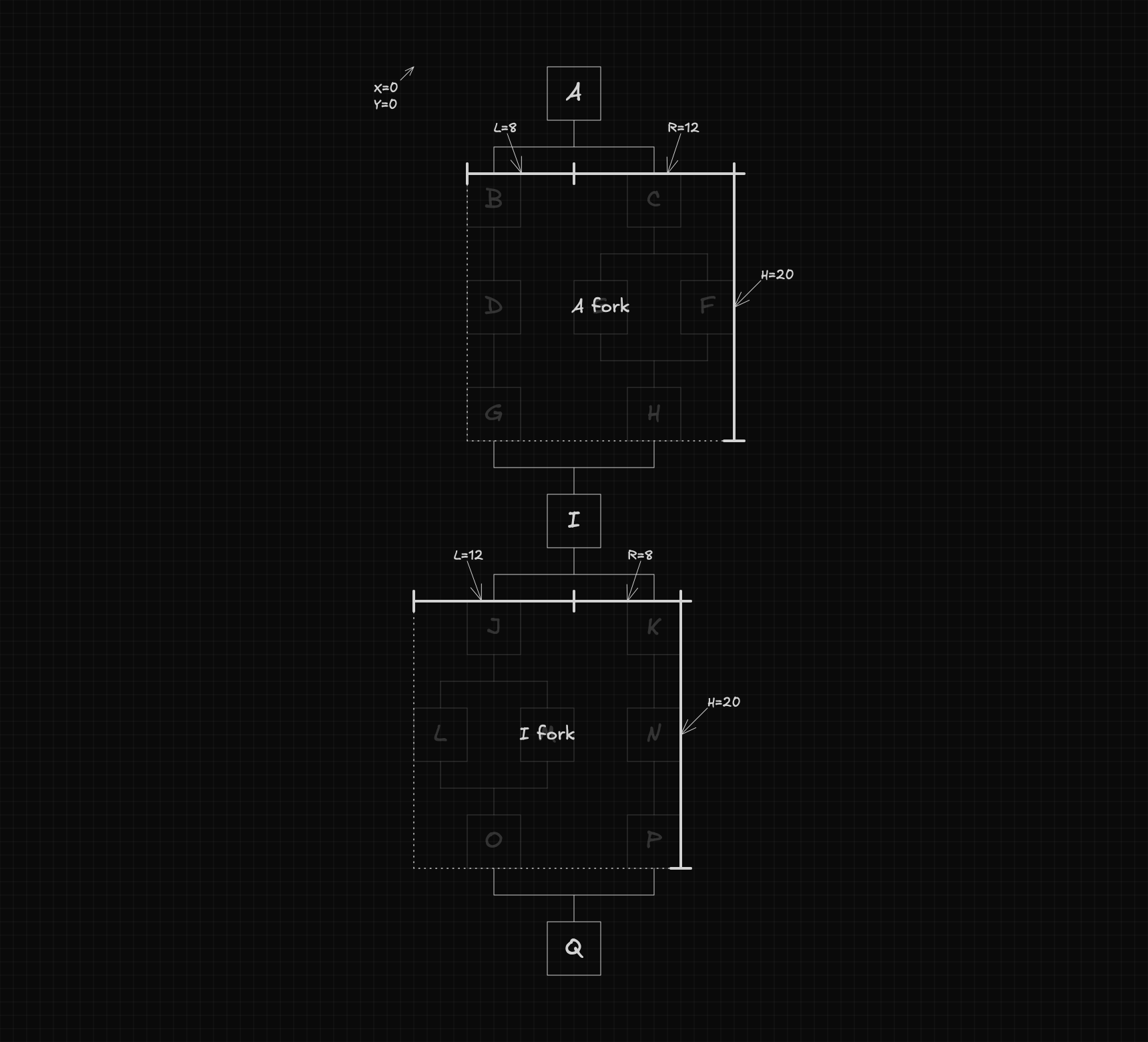
To compute node positions, we can simplify the problem by treating each fork as a single element.
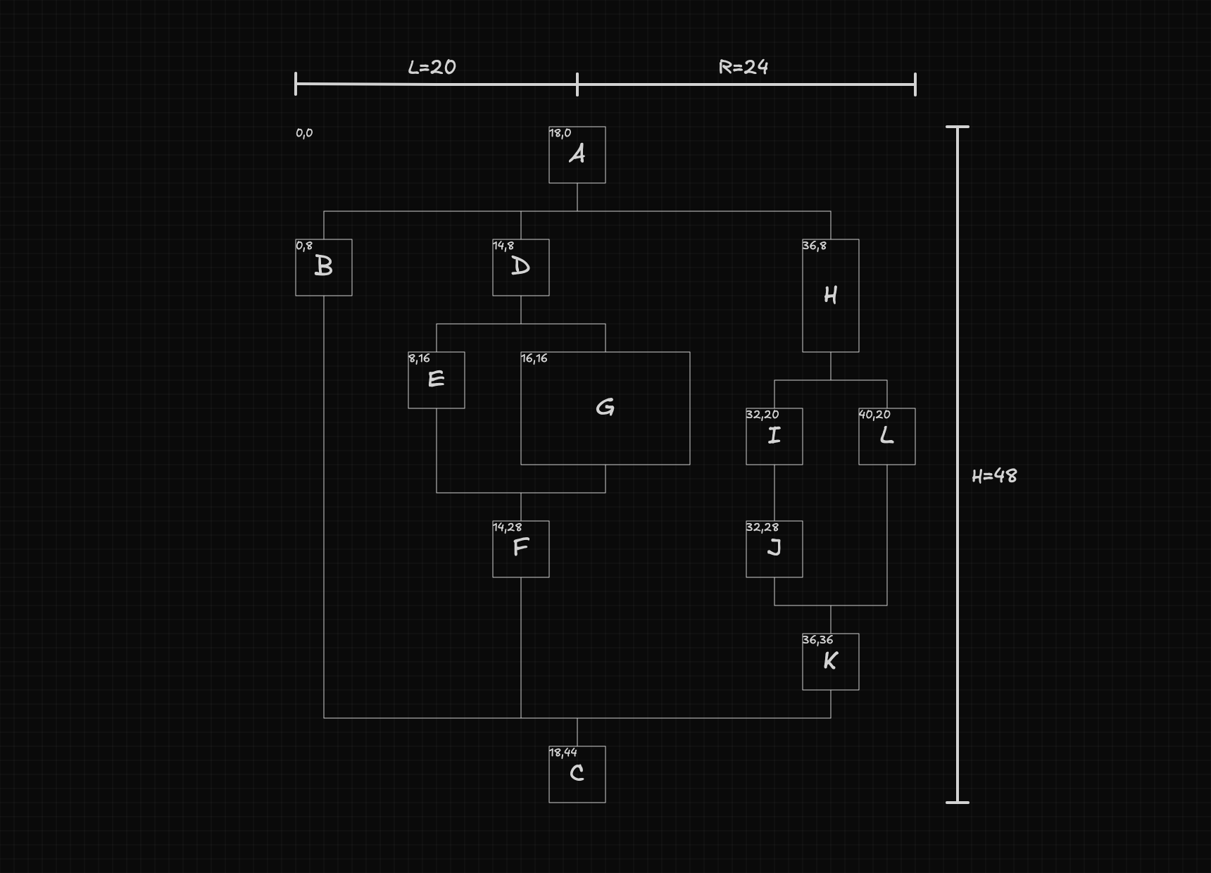
Next, we need to identify what information is required to calculate the positions of the nodes and forks. Specifically, we'll need the dimensions of the flow and each fork, as shown below:
With these dimensions, computing positions becomes straightforward. The calculations are as follows:
The function responsible for computing these positions can be defined as:
function setPositions(
  node: Node,
  position: {
    x: number;
    y: number;
  },
  dimensions: DimensionsFlow,
) {
  // ...
}
The dimensions object contains the dimensions of the flow and its forks, and is defined as shown below:
interface DimensionsFlow {
  flow: {
    l: number;
    r: number;
    h: number;
  };
  forks: Record<string, DimensionsFork>;
}

interface DimensionsFork {
  fork: {
    l: number;
    r: number;
    h: number;
  };
  flows: Record<string, DimensionsFlow>;
}
Finally, the positions of all nested flows within each fork are computed recursively, with a new call made for each flow using its corresponding parameters.
Computing dimensions
Before we can compute the positions, we first need to create the dimensions object. This object can be generated using the following function:
function getDimensionsFlow(node: Node): DimensionsFlow {
  // ...
}
This function internally computes the dimensions of each fork by calling:
function getDimensionsFork(node: Node): DimensionsFork {
  // ...
}
Using the data returned from these forks, it then becomes straightforward to calculate the overall dimensions of the flow with the following formulas:
The getDimensionsFork function, in turn, calls getDimensionsFlow to compute the dimensions of each flow within the fork. Using this information, it calculates the dimensions of the fork as follows:
Final steps
Now that both functions are defined, the final step is to combine them. The function below uses them together to compute the position of each node and return the overall dimensions of the flow.
export function autoLayout(root: Node): { l: number; r: number; h: number } {
  const dimensions = getDimensionsFlow(root);
  setPositions(root, { x: 0, y: 0 }, dimensions);
  return {
    l: dimensions.flow.l,
    r: dimensions.flow.r,
    h: dimensions.flow.h,
  };
}
Explore the Code
The implementation lives in two GitHub repositories, a Node.js project with just the layout algorithm, and a React project with it integrated into a basic workflow editor built on top of React Flow.